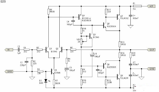
This is the 25W Class-A power audio amplifier circuit. The output devices are MJL4281A (NPN) and MJL4302A (PNP), and have high bandwidth, fantastic SOA (safe operating area), high linearity and high gain. Driver transistors are MJE15034 (NPN) and MJE15035 (PNP). All devices are rated at 350V, using the power transistors having a 230W dissipation and the drivers are 50W.
25W Class-A Power Audio Amplifier Circuit Diagram
- The supply voltage must be a maximum of ±25V. This supply is simply obtained from a 20-0-20V transformer, recommended current is 1A.
- All resistors ought to be 1/4W or 1/2W 1% metal film for lowest noise, with the exception of R9, R10 and R15 which ought to be 1/2W varieties, and R13, R14 have to be 5W wirewound.
- Using the suggested and advised 25V supplies, Q4 will typically not need a heatsink. The output drivers (Q5 and Q6) recommended to use a heatsink, even though it doesn’t have to be big.

